

Two proven measurement technologies, air gauging and inductive electronic probes, combined in a single ecosystem. This page explains the physics behind both, so you can understand exactly how your parts are being measured.
Air gauging is a non-contact dimensional measurement technique that uses controlled air flow to determine the distance between a nozzle and a workpiece surface. The principle has been used in industrial metrology since the 1920s, and remains one of the most accurate and reliable methods for measuring cylindrical features.
The concept is simple: regulated compressed air flows through a precision orifice and exits through nozzles in the gauging tool (an air plug for bores, an air ring for shafts). As the tool is brought close to the workpiece surface, the escaping air is restricted. This restriction causes back-pressure to build up in the measuring circuit.
The relationship between the clearance gap (distance from nozzle to surface) and the back-pressure is highly linear within a defined measuring range, typically 20 to 200 micrometers. By measuring back-pressure, we can determine the gap size with sub-micron precision.
Think of it like a garden hose aimed at a wall. Move the wall closer, water flow is restricted and pressure builds up in the hose. Move the wall away, water flows freely and pressure drops. Air gauging works on the same principle, but with filtered, regulated compressed air and precision nozzles instead of a garden hose.
The air itself serves a dual function: it is both the measurement medium and a cleaning agent. The pressurized air jet blows away oil, coolant, and chips from the workpiece surface before the measurement is taken. This makes air gauging uniquely suited for shop-floor environments where parts are still wet or dirty from machining.
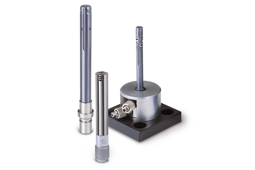
PFL air plug, precision nozzles visible on the gauge body
From calibration to reading, every measurement follows the same three-step sequence.
Before measuring, the air gauge is calibrated using two precision setting masters, one at the minimum tolerance and one at the maximum. The system reads the back-pressure at both sizes and establishes a linear scale between them. Masters should be 10–15 times more accurate than the tolerance being measured.
The air plug is inserted into the bore (or the air ring is placed over the shaft). Air flows through the nozzles and the gap between the nozzle face and the workpiece surface determines the back-pressure. Measurement is instantaneous, the display shows the actual dimension relative to the calibrated range. No special operator skill is required.
The display shows the deviation from nominal, plus OK/NOK indication based on tolerance limits. Multiple nozzle pairs simultaneously measure diameter, roundness, taper, and straightness. Data can be logged automatically for SPC, exported via RS-232, or fed directly to the CNC for process correction.
Understanding when air gauging outperforms traditional contact methods, and when electronic probes are the better choice.
| Characteristic | Air Gauging | Contact Probes |
|---|---|---|
| Contact with Part | Non-contact air jet only | Physical contact via ball or flat tip |
| Surface Damage Risk | ✓ Zero risk, no marking | ● Possible on soft/polished surfaces |
| Self-Cleaning | ✓ Air jet cleans before measuring | ● Requires clean surface |
| Repeatability | 0.1 μm achievable | 0.02 μm (PRETEC probes) |
| Measuring Range | Narrow (20–200 μm typical) | Wide (up to ±4 mm) |
| Best For | Bores, shafts, diameter & form | Depths, heights, positions, lengths |
| Shop Floor Use | ✓ Immune to oil, coolant, chips | Good with proper protection |
| Multiple Features | Multiple nozzle pairs simultaneously | Multiple probes in fixture |
| CNC Interface | ✓ Analog signal for real-time feedback | ✓ Analog or digital output |
| Geometric Checks | Roundness, taper, straightness, concentricity | True position, parallelism, perpendicularity |
The PFL approach: We don't force a choice. Most of our measuring benches combine both technologies, air gauging for bore and shaft diameters (where non-contact excels) and PRETEC electronic probes for depths, heights, and positional features. The same display system handles both signal types, giving you a complete dimensional picture in a single loading cycle.
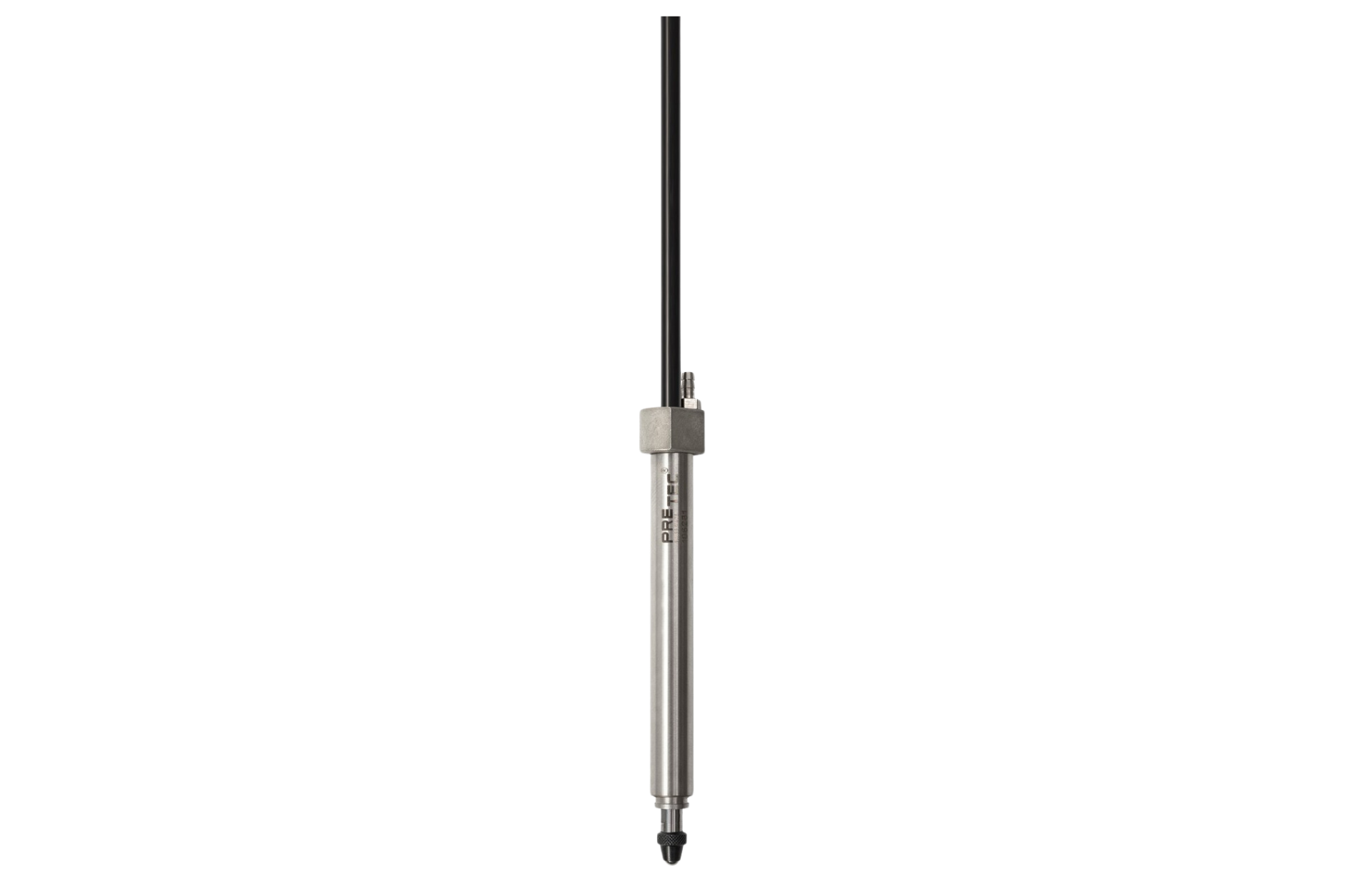
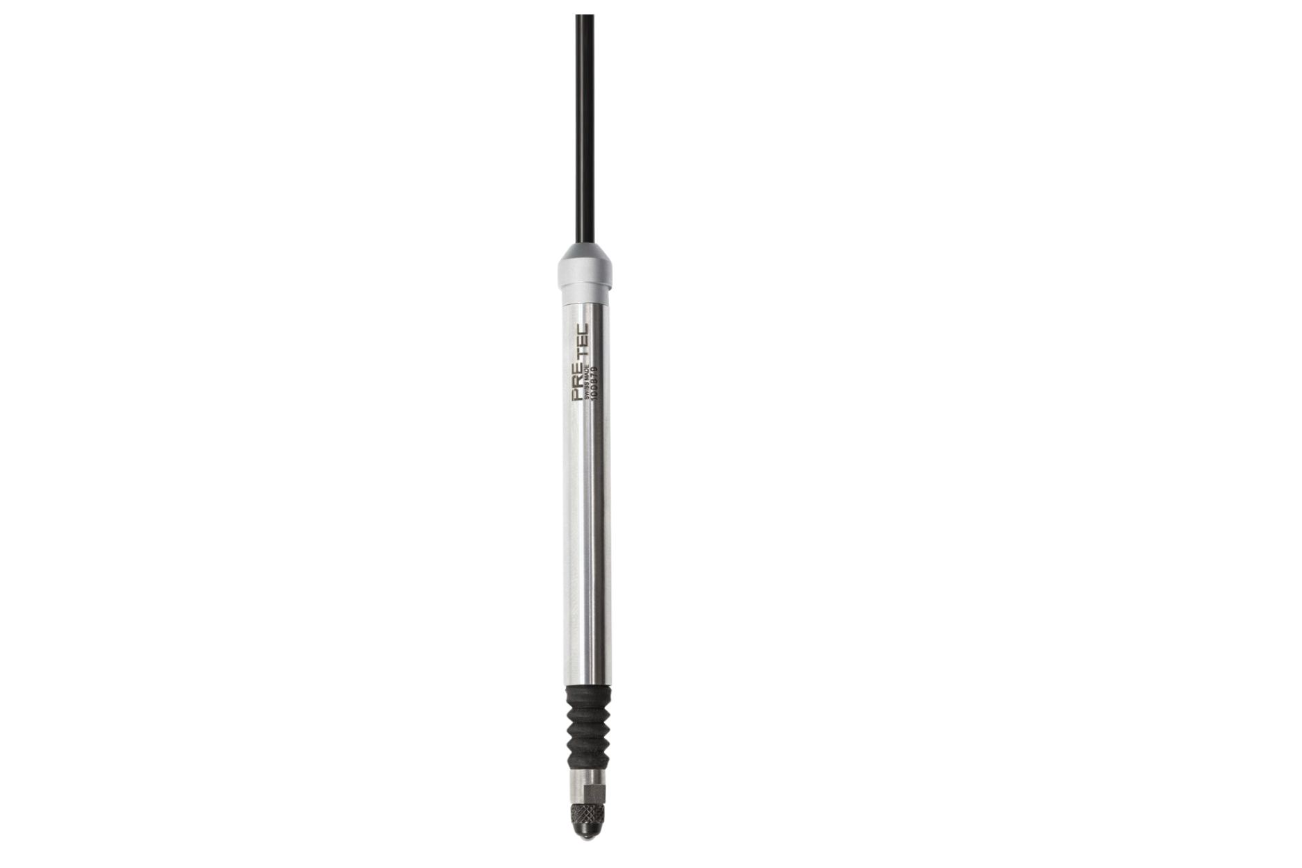
PRETEC electronic probes work on the inductive half-bridge principle, a measurement technology with over 100 years of proven industrial application. The concept is based on the interaction between a ferromagnetic core (the measuring bolt) and a coil system inside the probe body.
When the measuring bolt moves, pushed by contact with the workpiece, its ferromagnetic core shifts position within the coil system. This movement changes the inductance (the alternating current resistance) of the coil. The change is very small, but it can be measured with extreme precision using a Wheatstone bridge circuit.
In the half-bridge configuration, the probe contains two coils arranged so that when the core moves, one coil's inductance increases while the other decreases. This differential arrangement provides excellent temperature compensation and doubles the sensitivity compared to a single-coil design. The coils are supplied with an alternating carrier frequency of 13 kHz.
Half-bridge vs. full-bridge: A half-bridge probe has two active coils (two arms of the Wheatstone bridge), while the other two arms are completed inside the display unit. PRETEC probes are switchable — the bridge configuration can be changed at the customer site by switching inside the connector, providing compatibility with TESA and other major display systems without replacing the probe.
The mechanical construction is equally important: the measuring bolt is ball-bearing guided with an additional roller bearing to prevent rotation. The body is carbide-chromed for wear resistance. Pre-travel and post-travel are continuously adjustable. The result is a probe that delivers sub-0.02 μm repeatability even under harsh shop-floor conditions.



Each tool type is designed for a specific measurement geometry. The nozzle configuration, number of jets, and gauge body design are optimized for the feature being measured.
For internal features, bore diameters, roundness, taper. Two or more nozzle pairs measure diameter at multiple heights simultaneously. Available from Ø 0.5 mm.
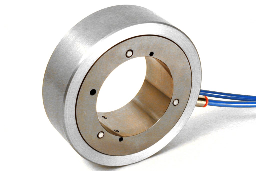
For external features, shaft diameters, roundness, cylindricity. The workpiece is inserted into the ring and nozzles measure from the outside in. Non-contact protects ground surfaces.

For ISO and HSK tool holder tapers. Dedicated air plugs and rings measure taper angle, diameter at gauge line, and runout. Standard ISO 30–50 and HSK A/E/F configurations.

Open-jaw design for external features that can't be enclosed in a ring. Measures flat surfaces, widths, and external dimensions where ring access is not possible.
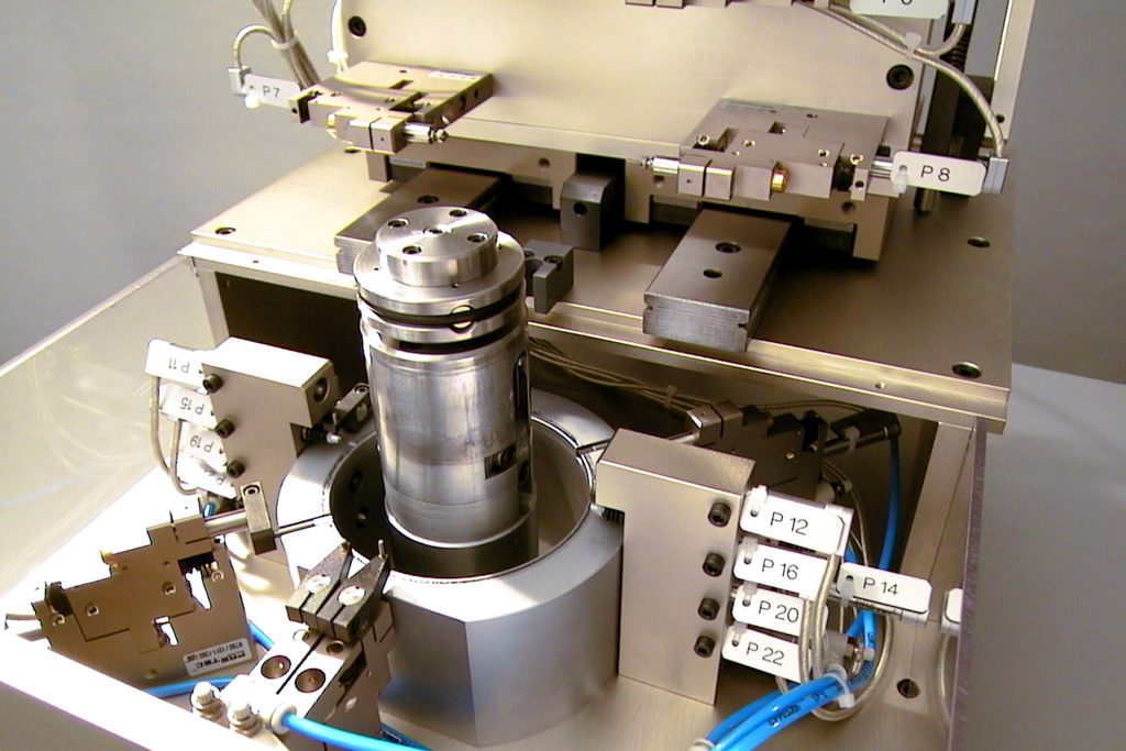
Most real-world inspection requirements involve both bore diameters and linear dimensions, diameter plus depth, or outside diameter plus shoulder position. Rather than using separate measurement systems, PFL combines air gauging and electronic probes into a single measuring bench with unified signal processing.
Our displays and software accept both signal types simultaneously. Air-to-electronic converters translate the pneumatic back-pressure signal into a standard electronic output, allowing it to be processed alongside PRETEC probe signals in the same data chain. One display, one measurement cycle, one SPC dataset.
Tell us what you need to measure. Our engineers will recommend the optimal combination of air gauging and electronic probes for your application.