

Non-contact dimensional measurement using controlled air flow. The fastest, most reliable method to inspect bore and shaft diameters on the production floor, with sub-micron repeatability.
Air gauging, also known as pneumatic measurement, is a non-contact dimensional measurement technique used primarily to inspect cylindrical workpiece features such as bore and shaft diameters. It works by directing a precisely regulated stream of compressed air through nozzles in a gauging tool. The back-pressure generated by the gap between the nozzle and the workpiece surface is directly proportional to the dimension being measured.
This principle has been trusted in industrial metrology since the 1920s, and remains the preferred method in high-volume production environments where speed, accuracy, and operator independence are critical. Because the measurement is non-contact, there is zero risk of scratching, marking, or deforming the workpiece, making air gauging ideal for highly polished, thin-walled, or soft materials.
The pressurized air jet also acts as a self-cleaning mechanism. Before each measurement, the air flow blows away residual coolant, oil, chips, and other contaminants from the measuring zone. This eliminates the need for a separate cleaning step, and allows accurate inspection of parts that are still wet from machining.
PFL air gauging systems combine pneumatic measurement with electronic signal processing. The back-pressure signal can be displayed on analog columns, digital readouts, or fed directly into SPC software and CNC machine controllers for automated process correction.
Repeatability down to 0.02 μm with double-lip plugs. Magnification up to 5,000:1.
No mechanical contact means zero risk of damaging polished, soft, or thin-walled surfaces.
Air jet removes oil, coolant, and chips automatically before each measurement.
No special training needed. Different operators achieve identical results on the same part.
Measurement takes seconds. Multiple features inspected simultaneously in one insertion.
No moving parts in the gauge. Robust carbide nozzles withstand harsh production environments.
Multiple nozzle pairs measure diameter, roundness, taper, and straightness in one shot.
Analog/digital output for SPC data logging and real-time CNC machine offset correction.
Each gauging element is designed for a specific measurement geometry. The nozzle configuration, body diameter, and number of air jets are matched to the feature being inspected.
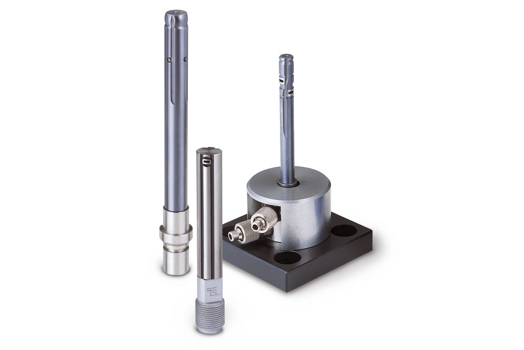
For internal measurement of bore diameters. Two or more nozzle pairs positioned at 180° or 90° intervals to measure diameter, roundness, cylindricity, and taper simultaneously. Available from Ø 0.5 mm upward with double-lip or simple-lip configurations.
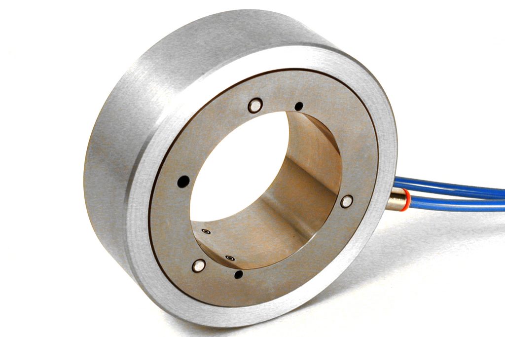
For external measurement of shaft diameters and cylindrical outside features. The workpiece is inserted into the ring, and nozzles measure from outside in. Ideal for ground or polished shafts where contact measurement would leave marks.

Dedicated air plugs and rings for inspecting tool holder tapers. Measures taper angle, diameter at gauge line, and runout. Standard configurations for ISO 30/40/50 and HSK A/E/F types used in CNC machine tool spindles.

Open-jaw design for measuring external features that cannot be enclosed in a ring. Measures flat surfaces, widths, and external dimensions on workpieces where ring access is geometrically impossible.
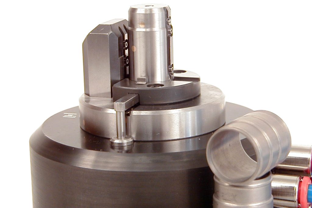
Air converters regulate and distribute compressed air to multiple gauging circuits. Air-to-electronic converters translate the pneumatic back-pressure signal into a standard electronic output, enabling unified display alongside PRETEC inductive probes.
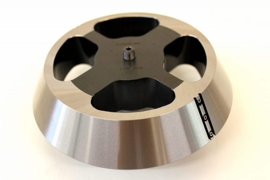
Every air gauge requires at least two precision setting masters (min and max) for calibration. We supply certified masters ground to tolerances 10–15× tighter than your workpiece tolerance, with traceable calibration certificates.
Achievable repeatability depends on the plug configuration and the measuring field (range). Narrower ranges yield higher precision. All values assume correct air preparation and proper introduction gap.
| Measuring Field → | ± 5 [μm] | ± 10 [μm] | ± 20 [μm] | ± 40 [μm] | ± 80 [μm] |
|---|---|---|---|---|---|
| Plug with 2 jets at 180° | 0.2 μm | 0.4 μm | 1 μm | 2 μm | 3 μm |
| Plug with 4 jets at 90° | 0.1 μm | 0.2 μm | 0.5 μm | 1 μm | 2 μm |
| Plug with double lips Up to Ø 15 mm diameter |
0.02 μm | 0.05 μm | — | — | — |
| Plug with simple lip, direct Starting from Ø 0.01 mm holes |
0.02 μm | 0.05 μm | — | — | — |
Important: The repeatability values shown are achievable when all parameters in the measuring chain are correctly maintained, including proper air supply pressure (3 bar filtered and dry), correct introduction gap, suitable tube diameter and length, and calibration with setting masters of appropriate accuracy. To validate these repeatability values for your specific application, an analysis by one of our measurement engineers is recommended.
PFL air gauging systems are designed to perform reliably in real manufacturing conditions, not just in temperature-controlled laboratories. Every component, from the carbide nozzles to the stainless steel bodies, is engineered for long service life under continuous production use.
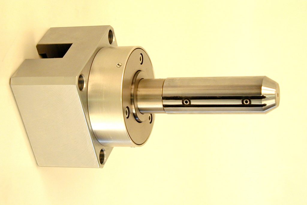
PFL air plug - precision nozzles visible on the carbide-chromed gauge body
A comprehensive range of accessories allows you to adapt PFL air gauging elements to your specific application setup. All accessories are available as standard catalog items or customized to your requirements.
Air plugs, air rings, and setting masters are designed and manufactured to match your specific workpiece requirements. Here is what we need to provide you with the correct solution.
Tell us what you need to measure. We need to understand the workpiece geometry and the measurement task.
A dimensioned part drawing is the fastest way to ensure we propose the correct gauge configuration.
Our engineers will design the optimal gauging solution and deliver a complete package ready to measure.
Everything you need to know about pneumatic dimensional measurement, from basic principles to maintenance and calibration.
Can't find the answer you're looking for? Our measurement engineers are happy to help.
Ask a Technical QuestionAir gauging uses controlled compressed air flowing through precision nozzles in a gauging tool. As the tool is placed near the workpiece surface, the escaping air is restricted by the gap between the nozzle and the part. This restriction causes back-pressure to build up in the measuring circuit. The relationship between gap size and back-pressure is highly linear within a defined range, so by measuring the pressure change, we can determine the dimension with sub-micron precision.
The concept is similar to holding your thumb over a garden hose, restricting the flow increases the pressure. In air gauging, this happens at a microscopic scale with filtered, regulated air at 3 bar pressure.
Repeatability depends on the plug configuration and measuring range. With a 4-jet plug at 90° and a ± 5 μm measuring field, you can achieve 0.1 μm repeatability. Double-lip plugs on small bores (up to Ø 15 mm) reach 0.02 μm, that's twenty nanometers.
The general rule is: the narrower the measuring range, the higher the repeatability. A ± 5 μm range gives the best results, while a ± 80 μm range offers more working tolerance but lower precision. Your PFL engineer will help you select the optimal range for your tolerance requirements.
PFL manufactures air plugs starting from Ø 0.5 mm (500 micrometers) for standard configurations. For even smaller bores, specialized direct-plug designs with simple lips can measure holes starting from Ø 0.01 mm, though these are application-specific designs that require engineering analysis.
At very small diameters, plug design becomes critical, nozzle size, body clearance, air flow volume, and the introduction method all need to be carefully matched to the bore geometry.
A two-master calibration system (MIN and MAX) establishes a known linear scale between two certified dimensional reference points. This means the display is calibrated at both ends of your tolerance range, providing verified accuracy across the entire measuring field.
A single-master system only calibrates the zero point. You are then relying entirely on the linearity of the readout electronics to be correct at the tolerance boundaries, which is an assumption, not a verified fact. For quality management systems under ISO 9001, IATF 16949, or AS9100, two-master calibration is strongly recommended and often required.
The industry standard recommendation is that setting masters should be 10 to 15 times more accurate than the tolerance of the workpiece being measured. For example, if your bore tolerance is ± 5 μm, your masters should have a size uncertainty of no more than 0.5 μm.
Masters are typically fabricated from hardened steel, chrome, or tungsten carbide, and are furnished to tolerances ranging from Class X to Class XXX. All PFL masters are supplied with traceable calibration certificates verified by comparison to certified gauge blocks.
Yes, and this is one of the biggest practical advantages of air gauging over contact measurement methods. The pressurized air jet (at 3 bar) that exits through the nozzles serves as a self-cleaning mechanism. It blows coolant, cutting oil, metal chips, and other contaminants away from the measuring surface before the measurement is taken.
This eliminates the need for a separate cleaning step in most production applications, and is a key reason why air gauging remains the preferred method for in-line and end-of-line inspection in automotive and hydraulic component manufacturing.
Yes, surface roughness does influence measurement results. An air gauge measures the average of the peaks and valleys within the area covered by the air jet, unlike a contact gauge (e.g., a dial bore gauge) which rides on the peaks only. This means air gauging effectively reports a mean diameter rather than a peak-to-peak diameter.
For best results, the surface roughness of the setting masters should be within approximately 1.3 μm Ra of the workpiece surface roughness. If your workpiece has a very different finish from the masters, a small systematic offset can appear. Your PFL engineer can advise on master specification based on your part's surface condition.
A stable, clean air supply is the most critical external requirement for accurate air gauging. The key specifications are:
Pressure: 3 bar regulated output (higher than 5 bar can damage the unit, lower than 2.5 bar degrades accuracy). Filtration: The air must be filtered and dried to prevent moisture condensation. Regulation: A precision pressure regulator is essential, standard shop regulators are usually not stable enough. Tubing: Use the recommended diameter and length of pneumatic tubing, as incorrect tubing causes slow response and unstable readings.
There are two levels of calibration to consider. Operational mastering (checking against setting masters) should be done at the start of each shift, after any interruption, and periodically during production, typically every 50 to 200 parts depending on your quality system.
Formal calibration of the complete system (gauge, masters, and display) should be performed according to your quality management schedule, commonly every 6 to 12 months. The setting masters themselves should be re-certified by an accredited laboratory at regular intervals, with traceability to national metrology standards.
Air gauges have an exceptionally long service life because there are no moving parts in the gauging element itself. The nozzles are typically made from carbide or hardened steel and the body is chrome-plated. In normal use, air plugs routinely last for hundreds of thousands of measuring cycles.
The primary wear mechanism is not the measurement itself (which is non-contact) but the insertion and removal of the plug from the bore. The rate depends on workpiece material, surface finish, and handling. Periodic wear checks using setting masters will indicate when a plug is approaching the end of its useful life.
Yes. A standard 2-jet air plug (nozzles at 180°) measures diameter across one axis. By using 4 jets at 90° intervals, the system simultaneously measures two perpendicular diameters. The difference between these readings indicates out-of-roundness (ovality).
Beyond roundness, air gauging can also check taper (comparing diameters at different heights along the bore), straightness, cylindricity, and concentricity between coaxial features. These checks are often performed simultaneously in a single plug insertion.
Air gauging excels where you need high speed, high repeatability, and operator-independent results on the production floor. If you're inspecting tight-tolerance cylindrical features in volumes above a few hundred parts per day, air gauging is almost always faster and more economical than a CMM.
A CMM is better suited for complex 3D geometries, first-article inspection, and low-volume high-variety work. A manual bore gauge is adequate for spot checks but introduces operator variability. In many facilities, air gauging handles 100% inline inspection while the CMM performs periodic audits and first-off verification.
Send us your part drawing and tolerances. Our measurement engineers will propose the optimal air gauging solution, including gauge type, configuration, masters, and display system.